

5 out of 5
Customer Reviews
Items 1 - 1 of 1 reviews
1
By
Karl Burgerhoffski
Date: January 13, 2017
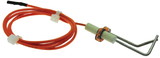
Yeah, but no better than the one I replaced, well maybe a little. You see, the flame sensor works by a Flame Rectification circuit. It is a phenomenon that was discovered. The history of which is very sketchy so it doesn't have a cool name like the "caldor effect". Kinda like the thermocouple, I think. The board will prove the flame by sensing a minimum draw of .4 ampere. It shoots out 24 VAC ( at a max value of .5 amp) and it is completed to ground as 24VDC (through the flame). So this is a 9.6 or 12 watt circuit. Low wattage circuits can do weird stuff if there is a bad connection, as if electricity wasn't already unpredictable . In my case the bad connection was at the board. That's right, I had to buy a new board for one hundred thirty dollars. The sensor plugs into a round thingy that looks like an amperage sensor to me. There may have been corrosion where the sensor plugs onto the board or some other anomoly.<br />Conventional advice is to look for a bad ground point. The flame touches all over the burner area so that ground should be good, right? I don't know, I checked the green and white wires with an O meter and all that.<br />Well it was the board. So bottom line is, 145 dollars later I'm staying warm without interruption. I'm keeping the old parts as spares, aka museum pieces. In theory, I could have tested the flame sensor, duh! What would you do?
Rating:  [3 of 5 Stars!]
[3 of 5 Stars!]
Items 1 - 1 of 1 reviews
1